Hello everyone !
Here is my new document about analog input and output application with Omron CP1H-XA40DT-D.

First of all , there are some settings which had should be arranged before doing application.

As you can see above each analog inputs can be set as a voltage input or current input.
In order to choose type of input , switch settings must be arrange according to Picture that i shared above.
Today , we are going read voltage with analog input thus , switches stay off in our application.
PLC SETUP

Each input’s input range is set independently in the PLC Setup.
The voltage input range can be set to 0 to 5 V, 1 to 5 V, 0 to 10 V, or −10 to 10 V.
The current input range can be set to 0 to 20 mA or 4 to 20 mA.
In our application we have arranged 0-10V because of our potentiometer range.
Now we are going to make wire connections between potentiometer and analog inputs.
Here is the explanation of analog input terminals.

Then let’s wired them !
First make connection with potentiometer and take these cable to the plc.

Input/Output conversion data is stored in CIO(Common Input Output) words between CIO 200 and CIO 211.

The analog voltage inputs are converted to digital values and output to CIO
words CIO 200 to CIO 203.
We wired potentiometer to analog input 5 and 6 pins which means analog value can be read from CIO 202 word.
CIO 202 can be read from Cx-Programmer when its online with CP1H PLC.
Do not forget the cycle the power to the PLC after the change settings !!! If you forget it there might be appear some occasional mistakes.
CI0 202 Value is 6000 in terms of decimal , because potentiomer’s output is adjusted to 5 Volt.

CI0 202 Value is 12000 in terms of decimal , because potentiomer’s output is adjusted to 10 Volt.

Analog output can be give with Cph1’s DA terminals.
We are going to measure output voltage from 9th and 11th terminals

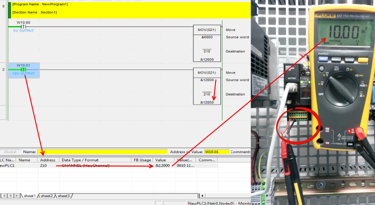
In order to give an output from 9th and 11th terminals , CIO 210 word must be assigned with a value with MOV command.
Firstly , built in AD/DA settings must be arranged.

You must ! cycle the power to the PLC after arrange setting above. If you forgot this , probably you’ll try to understand “why this plc is not giving output !” terms and started examine everyting 🙂
That is why please do not forget cycle the power !
After cycled operation is finished , when as soon as w10.00 contact is settled 1 , PLC’s 9th and 11th pins gives 5 Volt Output.

And as soon as w10.01 contact is settled 1 , PLC’s 9th and 11th pins give 10 Volt Output.

I wish you can understand how analog input and output works in CP1H-XA40DT-D plc. You might be have questions about that topic or another topic related with industrial automation components.
You can freely ask your questions from erhanesk.technic@gmail.com to me.
Next document that I planned to make related Mx2 speed settings with analog reference and multi-speed terminals.
See you in other useful documents !
Peculiar article, totally what I needed.
🙂
There’s certainly a great deal to learn about this topic.
I love all of the points you have made.
Thank you
What do you mean when you say “cycle de power”?
Hi Edward ,
What i mean with cycle the power is cutting energy of system and open it again.